What is a WHRU and what does it do?
A Waste Heat Recovery Unit (WHRU) recovers heat from hot gas streams – typically the hot exhaust from Gas Turbine Driven Generators or Compressor Sets which would otherwise be vented to atmosphere. The hot gas is cooled as it flows through a heat transfer coil (tube bundle) within the WHRU where heat is transferred into a process fluid (typically high-pressure hot water or Thermal Oil).
Typically, WHRUs operate within Offshore and Onshore Oil and Gas installations where there is a large demand for process heat. On a Floating Production Unit (FPU) there is a need to heat up the extracted crude oil so that it can be de-watered and brought to the correct viscosity for pumping.
On a gas platform, heat demand comes from amine re-boilers which are used to remove Hydrogen Sulphide from the gas stream (gas sweetening).
A WHRU is perfectly suited to these applications as they enable plant operators to capitalise on the exhaust gas emissions from their embedded power generators/mechanical drives to provide a large volume of process heat using a safe, low cost and extremely low maintenance technology.
What is the difference between a Circular and Traditional WHRU?
A WHRU is traditionally constructed with a ‘Serpentine’ tube bundle, where straight tubes are arranged in rows and connected by 180o return bends which sit outside the gas stream:
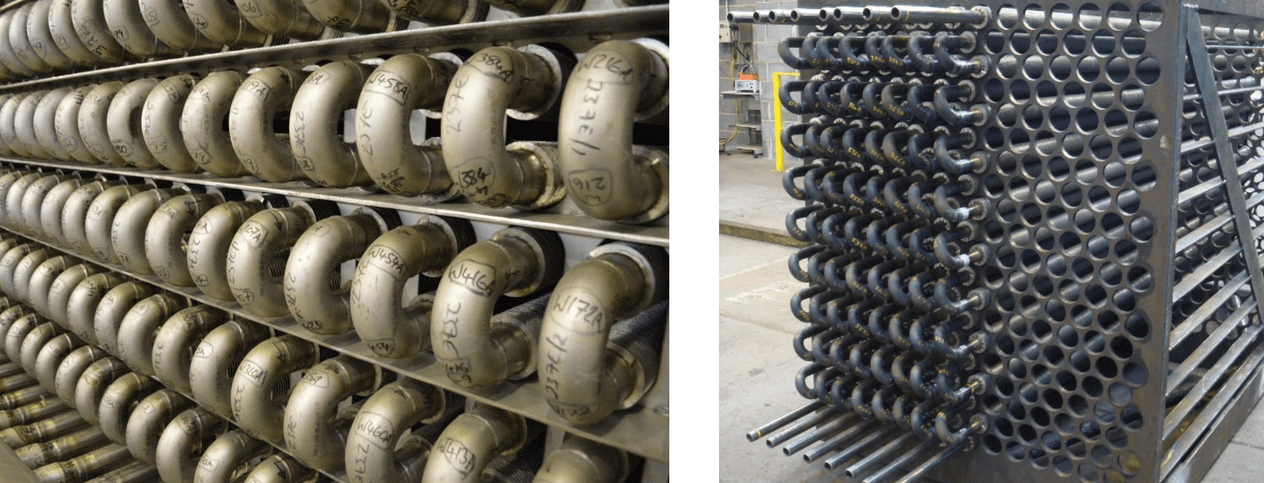
This method of tube bundle construction introduces many mechanisms for tube failure. The action of forming the tube into a tight return bend induces stress cracks within the material, greatly increasing the chances of a tube leak. There are some 80% more welds in a serpentine bundle, every weld is a potential point of failure and the return bends. To compound the issue, most manufacturers of serpentine bundles only carry out radiography on 10% of the pressure part butt-welds. CF Struthers carry out radiography on 100% of all pressure part butt-welds.
Serpentine bundles have an ‘effective length’ where because of the return bends, not all the tube length is located within the gas stream, meaning less efficient use of the piping and a heavier, larger bundle compared to a helical coil.
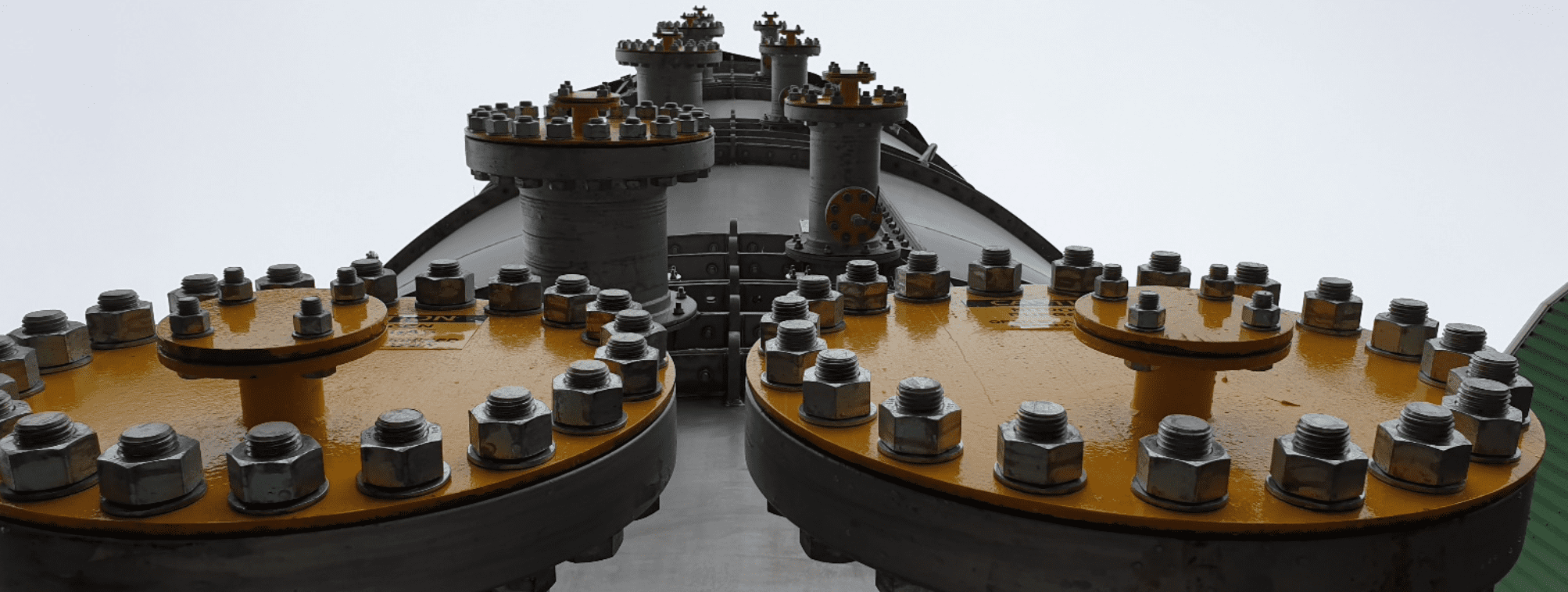
Packaging: Traditional WHRUs are typically designed with an external bypass which is requires large inlet and outlet transition casings to connect the bypass and coil ducts together, adding size and weight to the WHRU. A complex multi-louvre damper is then required to control the gas flow direction, the link arm system can be troublesome to set up and maintain.
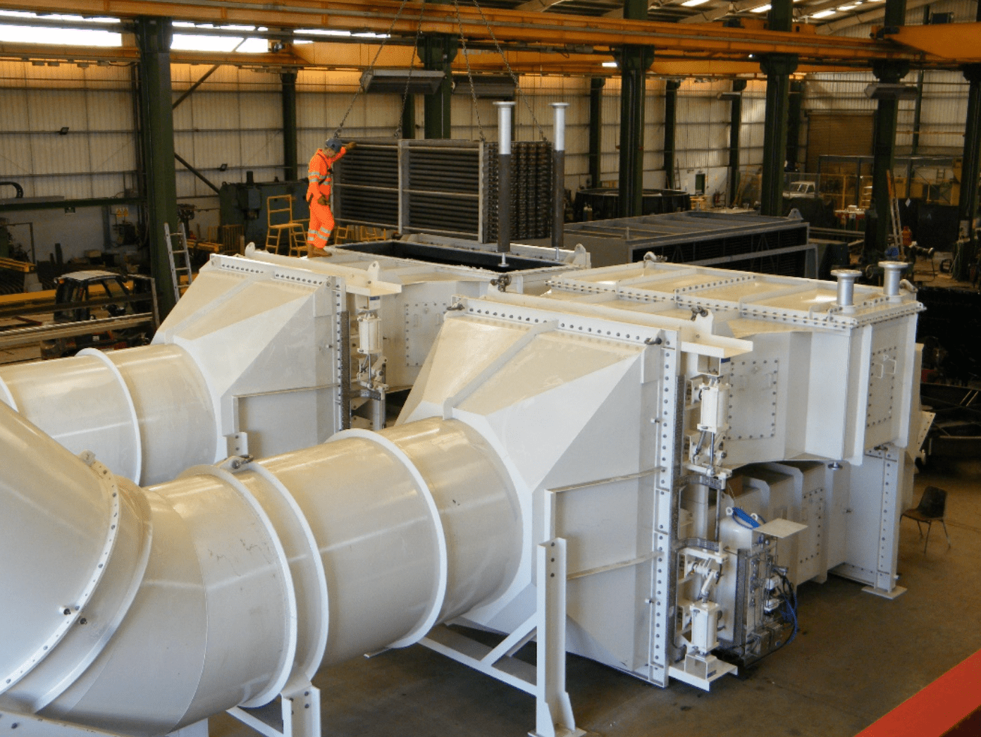
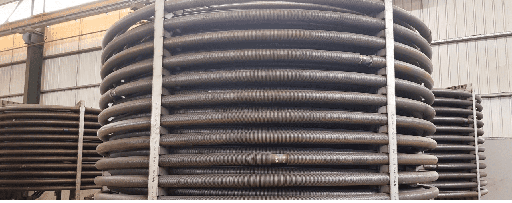
The Circular WHRU (CWHRU) is a significant advancement in WHRU technology, combining our in-house developed and Patented Contra-wound Helical Coil Manufacturing Process with our Patented Integral Radial Vane Bypass Damper. The resulting Circular WHRU offers a 30% weight reduction and up to a 70% footprint reduction when compared to a Traditional WHRU:
The design of the helical coil eliminates the need for return bends, hence the entire length of the tubing is located within the gas stream. There are no tight radius return bends and each tubing pass can be manufactured from 20m lengths meaning that the potential for tube and weld failure is dramatically reduced:
The design of our circular radial vane bypass damper means that the pivot shafts only span half of the WHRU diameter, they are also supported half way along the shaft. This short span and intermediate support means that the damper mechanism can be built of a lightweight construction which places much less stress on bearings and actuators. This damper design does not suffer from the sagging which can occur with the large span multi louvre traditional dampers during operation.
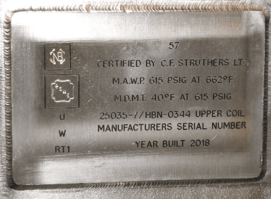
What is ASME BPVC?
The American Society of Mechanical Engineers Boiler and Pressure Vessel Code (ASME BPVC) is a comprehensive set of standards which regulate the design and construction of boilers and pressure vessels.
ASME works as an accreditation body who certify third party organisations to manufacture boilers and pressure vessels to the BPVC and carry the ASME Stamp. Recertification occurs every 3 years, thus ensuring that the quality and capability of ASME certified fabricators is regularly assessed.
CF Struthers are certified ASME S and ASME U Certificate holders, meaning that we are authorised to manufacture:
Power Boilers, Power Piping and associated parts according to the rules and regulations of ASME section I (ASME S-Stamp)
Pressure Vessels according to the rules and regulations of ASME Section VIII: Division I (ASME U-Stamp)
The ASME BPVC is an internationally recognised standard, equipment which is marked with the ASME stamp is a clear way of demonstrating that the equipment was designed and manufactured in accordance with stringent safety standards. It means that Clients, Operators, Regulators and Inspectors can be confident in the quality and safety of stamped equipment.
What is ASME S-Stamp?
An ASME S Certificate holder is authorised to manufacture and supply ‘Power Boilers’ and ‘Power Piping’, this means:
Boiler Proper Piping (BP): The piping internal to the boiler: Serpentine tube bundles, radiant coils, waterwall panels, superheaters, economiser bundles, downcomers and risers.
Boiler External Piping (BEP): The external piping directly connecting the boiler which is upstream of the first isolating valve, e.g. superheated steam line upstream of the main steam stop valve.
What is ASME U-Stamp?
An ASME U Certificate holder is authorised to manufacture and supply Pressure Vessels according to the requirements of ASME Section VIII: Division I. This is the specific section of the BPVC which addresses the design and manufacture of pressure vessels.
What is a Pressure Vessel?
A pressure vessel is a container which is used to hold a liquid or gas at a pressure which is significantly higher or lower than atmospheric pressure. A pressure vessel when in service places significant stresses upon the material forming the pressure retaining envelope and thus poses a significant safety risk should a failure/loss of containment occur. In order to mitigate this risk, pressure vessels are designed and manufactured in accordance with strict codes/standards. A number of standards are available to engineers in order to specify the design and manufacturing requirements for pressure vessels, these include:
■ASME Section VIII: Division I
■ PD5500
■ PED 2014/68/EU
■ EN 13445
■ EN 14015
■ API 650
What is an HRSG and what does it do?
A Heat Recovery Steam Generator (HRSG) or Waste Heat Recovery Boiler (WHRB) recovers heat from hot gas streams – typically the hot exhaust from Gas Turbine Driven Generators or Compressor Sets which would otherwise be vented to atmosphere. The various tube bundles within the HRSG capture the waste heat to raise steam, typically super-heated steam which is then used to drive a steam turbine to generate additional electricity. This is known as ‘Combined Cycle’ power generation.
An HRSG typically consists of three types of tube bundles or coils:
Economiser – Extracts the remaining energy within the exhaust gas to heat the incoming feedwater close to saturation temperature.
Evaporator – Takes the water discharged from the economiser and evaporates it to saturated steam
Superheater(s) – Takes the saturated steam from the separator (drum or cyclone), located at the front of the HRSG uses the high inlet exhaust temperature to raise the steam temperature to supply dry, superheated steam which can be used to drive a steam turbine.
Images below show a Circular-HRSG recently supplied by CF Struthers. The lower casing contains the primary and secondary superheaters. The two central casings contain the forced circulation evaporator coils. The upper section contains the economiser coil.
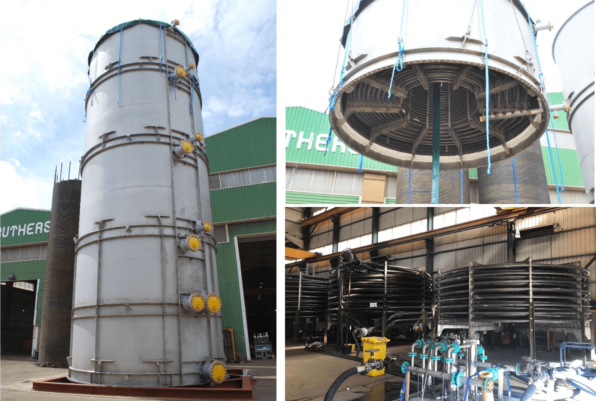
The helical coil which forms the basis of the HRSG also offers major reliability benefits through elimination of serpentine return bends and stress raising corners on rectangular casings.